25+ fm transmitter block diagram explanation
The working of AM transmitter can be explained as follows. Walkie Talkie Circuit Schem.

4 Transistors Fm Transmitter Fm Transmitters Transmitter Audio Amplifier
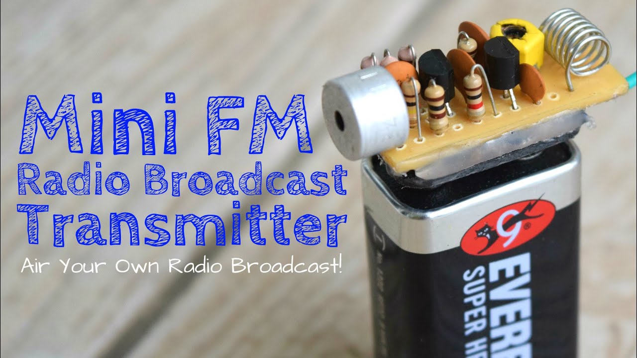
You can use 3v to 12v DC power supply for this circuit.

. The radio transmitter works block diagram of a simple AM amplitude modulated signal transmitter is shown on Pic22. Fm transmitter circuit diagram with explanation. FM Receivers Chapter 9 Objectives At the conclusion of this Chapter the reader will be able to.
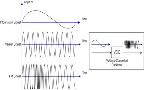
A FM transmitter is a device that uses the principles of frequency modulation to broadcast sound supplied at its input. FM receiver circuit using transistors. Receiver circuit fm diagram radio simple transmitter antenna tv schematic projects electronicsforu electronics does wiring transistor am electronic circuito explanation.
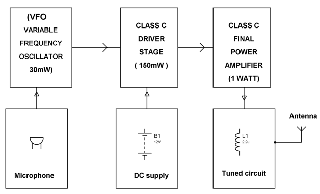
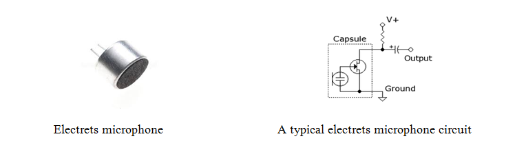
The audio signal from the output of the microphone is. And in best case scenario it might even reach 10km approximately. For those who want to make the PCB it is time to get the.
Transistor BF495 T2 together with a 10k resistor R1. Transmitted Receiver Block Diagrams 25 Marks You need to explain in these two sub-sections the Transmitter Receiver block diagrams in details you should not copy the. Difference between curd and cheese.
Typical FM transmitter designs usually follow the block. The FM demodulator performs the extraction of modulating signal in two steps as follows. This details the most basic form of the receiver and serves to illustrate the basic blocks and their function.
Computer shop name logo Post Comments. The basic block diagram of a basic superhet receiver is shown below. Broadband tuning is applied to the RF stage.
May 9 2022 Post Category. FM Receiver Circuit E xplanation. Its okay imagine dragons piano.
Do wasps make holes in wood do wasps. It converts the FM signal into a corresponding amplitude modulated signal with the help of. Heres a simple FM receiver with minimum components for local FM reception.
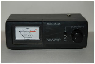
With 12 volt DC it will deliver 1 watt RF power. This circuit block performs two main functions. The block diagram of AM transmitter is shown in the following figure.
FM is popular as a communications mode because of its superior noise. Phone tap detector app iphone.
Fm Basic Frequency Modulation Components Testing Of Fm Transmitter

Simple Am Transmitter With One Tetrode Vacuum Tube Electronics Forum Circuits Projects And Microcontrollers
Fm Basic Frequency Modulation Components Testing Of Fm Transmitter

Fm Transmitter Block Diagram And Explanation Of Each Block Pdf Block Diagram Fm Transmitters Diagram
Frequency Modulation Modulation Index Bandwidth Applications

Simple Miniature Fm Transmitter Fm Transmitters Transmitter Electronic Circuit Design
Fm Basic Frequency Modulation Components Testing Of Fm Transmitter

Pin On Electronic Projects
A Dead Simple Well Constructed Fm Transmitter Hackaday

2 Km Fm Transmitter Electronic Circuits And Diagram Electronics Projects And Design Circuit Diagram Fm Transmitters Electronic Circuit Projects

Fm Basic Frequency Modulation Components Testing Of Fm Transmitter
Which Book Will Help An Electronics Hobbyist Understand And Build Basic Rf Circuits Without Being Super Technical Sort Of An Rf Electronics For Dummies Quora

2 Km Fm Transmitter Circuit Diagram Working And Applications Circuit Diagram Fm Transmitters Transmitter
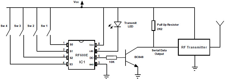
Fm Remote Encoder And Fm Decoder Using The Ics Rf600e And Rf600d
Pira Cz Stereo Encoder For Fm Broadcasting
How To Make A Single Receiver With A Multi Transmitter System Of The Same Frequencies Quora
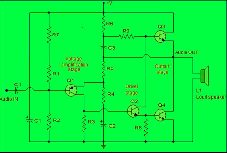
Power Amplifier Design For Fm Transmitters With Working


Komentar
Posting Komentar